1 2 3 4 5 6 7 8 9 10 11 12 13 14 15 16 17 18 19 20 21 22 23 24 25 26 27 28 29 30 31 32 33 34 35 36 37 38 39 40 41 42 43 44 45 46 47 48 49 50 51 52 53 54 55 56 57 58 59 60 61 62 63 64 65 66 67 68 69 70 71 72 73 74 75 76 77 78 79 80 81 82 83 84 85 86 87 88 89 90 91 92 93 94 95 96 97 98 99 100 101 102 103 104 105 106 107 108 109 110 111 112 113 114 115 116 117 118 119 120 121 122 123 124 125 126 127 128 129 130 131 132 133 134 135

46

These relationships allow us to attain final values for Qclose to the desired values for each step

using a simplified form of the Jacobian, discussed in the next section.


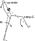
One interesting point to note is that the slope of the stance-COM curves in Figure 3.16 and Figure

3.17 are opposite in sign compared to the corresponding slopes for the up vector and swing-COM

RVs. This is due to the mechanism through which the stance-COM angle changes.

shows this effect exaggerated for clarity.


IMAGE Imgs/thesis.final.w675.gif

Figure 3.18

IMAGE Imgs/thesis.final.w676.gif

of M.

stance-C. of

Figure 3.18 - Direction of change of forward RV components with hip pitch


Linear, Sampled "Balance" Control

3. 7

This section describes how the base PCG, perturbations and various RVs discussed in earlier

sections can be used to compute and apply the discrete system model parameters (Jand Qnom) to

generate a balanced walk. The "balancing" is done by choosing appropriate RV target values for

each step and finding the scaling factors to apply to the PCG perturbations to reach them.

The

scaling factors are determined automatically using the inverse of the linear discrete system model

(Eq. 3.11). The balancing process is repeated, one step at a time, for as many steps as desired.

In some cases, the resulting walk is erratic and wanders.

reached.

In others,

a walking limit cycle is

[CONVERTED BY MYRMIDON]