 |
 |
 |
 |
 |
 |
 |
 |
 |
 |
 |
|
19
|
 |
|
|
|
 |
|
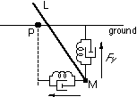
The ground reaction forces are modeled for all simulations using a spring and damper model.
|
 |
|
Figure 2.7 illustrates the model for a 2D system.
|
Ground forces are applied to specific, pre-
|
 |
|
defined monitor points on the model. on the model.
has penetrated the ground surface are:
|
The ground forces exerted on a monitor point, M, which
|
 |
|
F = = kp kp [!] [!] ( ( P P - - M M ) ) - - k k · ·
 d d [!] [!] M M
|
 |
|
where F is the ground reaction force, M is the ground reaction force, M is the position of the monitor point, is the position of the monitor point,  M · M ·  is its velocity, P is its velocity, P
is the initial point of contact with the ground, and  kp kp and and  kd kd are proportional and derivative are proportional and derivative
constants defining the stiffness and damping properties of the ground (see Figure 2.7).
|
 |
|

|
 |
|

The ground reaction forces are bounded such that the vertical component is always positive, thus
|
 |
|
never allowing the damping term to impede the lifting of the foot.
|
Monitor point slippage is
|
 |
|
implemented using a Coulomb friction model, which is used to limit the tangent of the ground
|
 |
|
reaction force.
|
Slippage is allowed when the ratio of the vertical and tangent forces exceeds  a a
|
 |
|
specified limit as illustrated in Figure 2.8 for the 2D case.
point of initial contact, P, to be directly above monitor point.
|
Slippage is simulated by moving the
|
 |

 1
2
3
4
5
6
7
8
9
10
11
12
13
14
15
16
17
18
19
20
21
22
23
24
25
26
27
28
29
30
31
32
33
34
35
36
37
38
39
40
41
42
43
44
45
46
47
48
49
50
51
52
53
54
55
56
57
58
59
60
61
62
63
64
65
66
67
68
69
70
71
72
73
74
75
76
77
78
79
80
81
82
83
84
85
86
87
88
89
90
91
92
93
94
95
96
97
98
99
100
101
102
103
104
105
106
107
108
109
110
111
112
113
114
115
116
117
118
119
120
121
122
123
124
125
126
127
128
129
130
131
132
133
134
135
1
2
3
4
5
6
7
8
9
10
11
12
13
14
15
16
17
18
19
20
21
22
23
24
25
26
27
28
29
30
31
32
33
34
35
36
37
38
39
40
41
42
43
44
45
46
47
48
49
50
51
52
53
54
55
56
57
58
59
60
61
62
63
64
65
66
67
68
69
70
71
72
73
74
75
76
77
78
79
80
81
82
83
84
85
86
87
88
89
90
91
92
93
94
95
96
97
98
99
100
101
102
103
104
105
106
107
108
109
110
111
112
113
114
115
116
117
118
119
120
121
122
123
124
125
126
127
128
129
130
131
132
133
134
135

