Produce a functional digital object. A functional object is one that is hooked
up with controls that simulate its operation. For example, a bicycle model should
have pedals whose rotation causes the drive train to turn the rear wheel. You can
use any modeling and texturing software, including scanning physical pieces. Part of
the purpose is to make you familiar with existing modeling workflows and tools. Choose
your object representations as meshes, patches, or subdivision surfaces based on the
kind of model you are building. The final model assembly should be put together in Maya
and example renderings should showcase the design. Try and be as creative and artistic
as you can.
idea
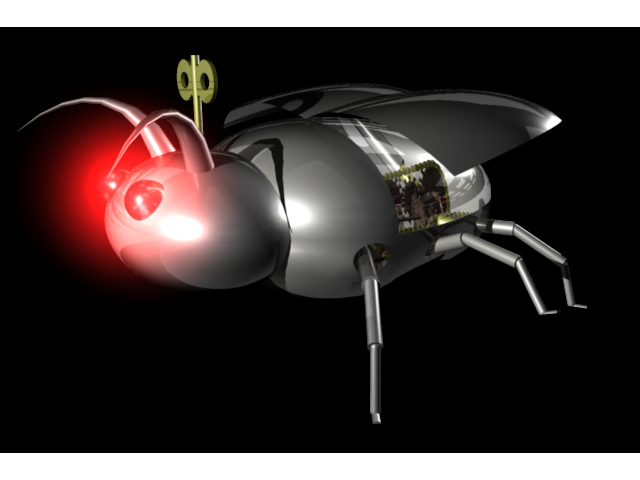
I wanted to have a model with clunky mechanical working parts,
such as gears and chains, but have them contained within a
smooth polished shell casing. Polygonal objects modified with
boolean operations would give the right look for the mechanical
parts. As for the shell, I wanted to experiment with NURBS patches
as I haven't had much experience with them. They would provide the
right look for both the geometry and shading, and I also wanted to
play with NURBS surface ops (attaching, detaching, trimming, etc).
I did not base the model on any real-world physical object. I
simply saw the object in my mind and had to translate that idea
into the digitial domain. This turned out to be a good exercise
in understanding the human 'video out' dilemma (see the Project
Description for MITACS).
modeling - parts
Body - bodyProject.ma
Constructed from a NURBS sphere appropriately cut, scaled, and
stitched back together. The wings are each a quarter hemisphere
with limited rotation angles about the attachment point. Since
the lower body was sculpted to fit the gears inside, it was
necessary to move the seam to the opposite side of the surface than
was being sculpted. The surface is not closed, as doing so introduced
slight surface distortions (shading was not affected in the end).
Leg - legProject.ma
Composed of several cylinders parented together. Spheres were
used at the junctions to smooth the joints. The foot is a cylinder
boolean differenced with a rectangular parallelepiped. The rounded
cylinder coming out of the top part of the leg is the piston which
connects the leg to the gear chain.
Gears & Chain - gearProject.ma
Definitely the most involved part of the model. The gears are cylinders
boolean differenced with some cubes to create the teeth. Interesting
fact about gear ratios and the number of teeth:
The chain links are oblong cylinders mixed together with some cubes
using boolean ops. Actually, there is only one link; all the others
are just instances. To animate the chain around the gears, a motion
path was used. The links were attached to the motion path and offset
appropriately along the curve.
Antenna - antennaProject.ma
A NURBS surface generated by sweeping a circle along a curve and
scaling along the way.
Turnkey - turnKeyProject.ma
Four cylinders unioned together and then differenced with two
others (all boolean ops).
modeling - the bug
The Bug - projectFinal.ma
This is where it all comes together. The only parts that don't
have their own project are the head, the main gear shafts, and
the supports (left as an exercise for the reader). Duplicated
parts are copied rather than instanced, as some weird things
happen when constraints are made (don't know why). The lower
body is trimmed to allow the legs to come through. The legs are
aim constrained to a locator on the respective chain. The leg
pistons are parented to said locators and aim constrained to
the respective leg. The turnkey drives the entire mechanical
operation, which is specified using multiple expressions on
both the turnkey and the gears.
shading
The look I wanted to capture was a shiny metal shell with red
glowing eyes; the exterior should look new. On the inside, though,
I wanted a more worn and weathered look, something that showed
a little age. I was able to find some extraordinary shaders over
at Highend3d.com to accomplish just that.
Beavasoft Chrome Shader 1.0
Used for the external shell casing, antenna, and legs. I created
a gold variant of this shader for the turnkey, leg pistons, and
chain links.
Gie Red Jade 1.0
Used for the eyes. The jade texture along with the glow effect
gives the eyes a nice electric appearance.
TrueGlass 2.5
An amazing glass shader. Used for the cover encasing the gears.
denfo Old Paint 0.0
Used for the gear shaft supports. Gives a nice worn look.
Old Rusty Metal 1.0
Used for the gears and gear shafts. Gives a nice worn look.
The design and construction of a functional model just
wouldn't be complete without a demonstration of the model
in action. Here are some animations (mp4 format) for your
viewing pleasure (animations correspond to the position of
the model as shown above):
Note: Due to the speed at which the bug walks, there is
temporal aliasing occurring in the animations. I assure you,
however, that everything mechanically works correctly.
Due to popular demand, here are some pics of the scene
graph for the final project. I'm sure it's nothing compared
to other scenes out there, but it seemed to draw quite a few
looks here at the lab. It's really quite easy to understand
(if you know what you're looking at). You can see the bug
cluster over on the right side of the top image. What, you
don't see it? Well, the bottom image is a close-up of it.
I made extensive use of the scene graph to setup constraints,
break / create node connections, etc.
Remember, the scene graph is your friend.
mike pratscher
graduate student
dynamic graphics project
university of toronto
map [at] dgp [dot] toronto [dot] edu