 |
In this section:
In RenderDude!, a camera is an entity that implements a particular visibility determination/rendering algorithm. RenderDude! currently contains two camera types. The first camera type implements a software z-buffer scanline algorithm. The second camera type implements Ned Greene's hierarchical coverage mask algorithm, as presented at Siggraph '96.
The two cameras differ in how they resolve visibility, but both support the same four shading options:
The following sections describe the rendering algorithm implemented by each camera.
This camera implements a simple z-buffer visibility algorithm, with one visiblity sample being taken per pixel (at the centre of the pixel). The rendering process for this camera goes as follows:
foreach object i tessellate object i into polygons end foreach frame in animation update all animated attributes foreach object o project o's tessellation into screenspace foreach face f render face f using a z-buffer algorithm end // face rendering end // object rendering end // frame rendering |
CamZB permits the camera as well as any geometry and shading parameters to be animated.
Each polygonal face is triangulated, then scan converted using an incremental scanline algorithm. For Gouraud shading, vertex colours are interpolated in the scan conversion process. For Phong shading, affine coordinates are interpolated along each span. At each shading sample point, the interpolated affine coordinates at that point are used to construct the necessary shading sample data (position, normal, texture coords, etc).
This camera implements Ned Greene's hierarchical coverage mask visibility algorithm, as described in his Siggraph '96 paper. The visibility sample positions in the image are organized into a quadtree structure called the coverage pyramid, which maintains cumulative visibility information as polygons are tiled in a strict front-to-back order.
Each node in the coverage pyramid represents the visibility samples contained in a specific region of the image. Each node uses a triage mask to maintain the status (covered/uncovered) of its visibility samples. A node's triage mask partitions the node's image region into a regular 8x8 grid of subregions. A triage mask is in fact a set of 3 bitmasks:
Leaf nodes in the coverage pyramid represent visibility using a single bitmask, in which each position represents the coverage status of a single visibility sample.
The algorithm supports two visibility sample resolutions - 1 sample per pixel or 64 samples per pixel (which I refer to as subpixel mode). In subpixel mode, the leaf nodes of the coverage pyramid represent individual pixels, and each bit in the leaf node bitmask represents one of 64 regularly spaced sample positions in the pixel. In non-subpixel mode, one visibility sample per pixel is taken, so the leaf node bitmasks each represent an 8x8 block of pixels, with each bit in the bitmask representing a visibility sample position at the centre of the corresponding pixel.
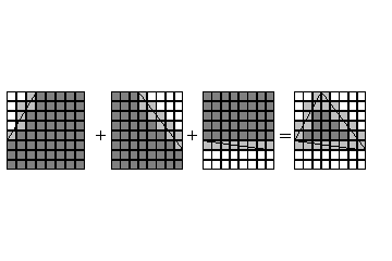
To tile a polygon into a particular node in the coverage pyramid, we first compute the triage mask for the polygon in that region. This is done by compositing together triage masks for the individual edges of the polygon, which have been precomputed and stored in a table indexed by the entry/exit points of the edge on the perimeter of the image square. The edge mask compositing process is illustrated in the following diagram (white regions are vacant, light grey are active, dark grey are covered):
 |
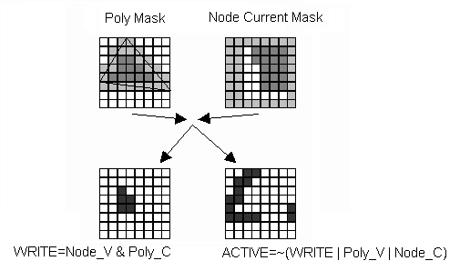
The resulting polygon triage mask is then combined with the triage mask in the coverage pyramid representing the accumulated visibility of all previous tiled polygons. This operation (shown in the diagram below) results in the computation of two new masks:
 |
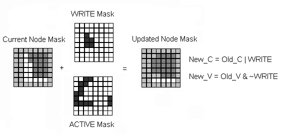
At this point, we know that the current polygon completely covers the subregions indicated by the WRITE mask, so we can render the current polygon into the image pixels for that subregion. The ACTIVE mask indicates regions in which the poly may be visible, so we recurse on those subregions. We then update the visibility at the current node using the two new masks as shown in the following figure:
 |
The final step is to propagate any new visibility information back up the coverage pyramid. For example, if a particular region becomes completely covered, we must ensure that the corresponding bit in the C mask of the node's parent is set.
To summarize, the steps for rendering a single polygon into a particular node in the quadtree are:
compute the polygon edge triage masks composite together the edge triage masks to form the polygon triage mask compute the WRITE and ACTIVE masks for the polygon using the current node's triage mask foreach bit b set in the WRITE mask shade all pixels in the image region corresponding to this bit end foreach bit b set in the ACTIVE mask recurse on the child node corresponding to this bit end update the current node's triage mask propagate visibility information back up the pyramid |
When the WRITE mask identifies a region of the image that is covered by a particular polygon, we need to shade the image pixels with the colour of that polygon. For each pixel to be shaded, I take a shading sample at the centre of the pixel. My algorithm first computes the affine coordinates of the pixel centre (in screen space). If Gouraud shading is enabled, these affine coordinates are used to interpolate the pixel colour from the vertex colours for the current triangle. If Phong shading is enabled, the coordinates are used to construct the appropriate shading parameters, and a shading sample is taken.
In subpixel mode, it is possible that multiple polygons may be visible in the same pixel. In this case, the computed colours for the individual polygons are box-filtered to produce the final pixel colour. This is accomplished by using the bitcount in the WRITE mask for the polygon as an estimate of its pixel area coverage. Since we take 64 visibility samples per pixel, this estimate is probably accurate enough, but the results would be improved by an exact area computation.
As mentioned above, the HCM algorithm requires a strict front-to-back traversal of all polygons in the scene. To this end, I have implemented the visibility structure described by Greene in his paper. First, an octree structure is computed encompassing all polygons in the scene. Octree nodes can contain a maximum of 50 faces. When a node reaches this limit, it is split into 8 subnodes, and its faces are clipped and distributed to the children. In this manner, only the leaf nodes of the octree actually contain faces when the octree is complete.
The leaf nodes of the octree are easily traversed in a front-to-back order, but the polygons within each node may not be ordered properly. We therefore construct a BSP tree for each octree leaf node. By traversing the leaf nodes front-to-back, and traversing polygons in each node front-to-back (as computed by the node's BSP tree), we obtain a complete front-to-back traversal of the scene. This approach is considerably faster than simply constructing a BSP tree for the entire scene, particularly when the polygon count is high, but it is still rather costly in terms of both memory usage and computation time.
Because the visibility structure is rather expensive to compute, the system ignores animated geometry when rendering using this algorithm. Handling geometry animation would require either complete recomputation of the octree of BSP trees structure at every frame, or the utilization of a sophisticated algorithm for computing and incrementally updating the visibility structure, which I chose not to implement. On this matter, Greene suggests that an octree could be constructed for each object individually, then object octrees could be merged at every frame, which would be cheaper than recomputing the entire structure.
Thus, animated geometry is ignored, but animated camera and shading parameters are permitted. The complete algorithm goes as follows:
foreach object i tessellate object i into polygons end accumulate individual object tessellations into one big scene tessellation construct octree from scene tessellation construct BSP trees for octree leaves foreach frame in animation update all animated attributes compute front-to-back face ordering for current camera position project scene tessellation into screenspace foreach face i in the scene tessellation compute the smallest enclosing coverage pyramid node n for face i compute the screenspace bounding box of face i test the bounding box for visibility, starting at node n if the bounding box is potentially visible tile face f into the coverage pyramid starting at node n endif end // face rendering end // frame rendering |
The main advantage of the algorithm is that visibility can potentially be determined very quickly for a given face. Say a particular polygon is completely contained in a particular coverage pyramid node that has already been completely covered by previously tiled polygons. In this case, there is a very good chance that the first bounding box test will determine that the polygon's bounding box (and hence the polygon itself) cannot possibly be visible, hence it can be discarded. The z-buffer algorithm would have to scan convert the entire polygon before it could determine that it was not visible. This benefit begins to add up as the depth complexity of the scene increases.
The main disadvantage to the algorithm is the requirement for a strict front-to-back traversal of the scene tessellation. In my implementation, I have observed that constructing the octree of BSP trees tends to increase the number of faces in the scene by anywhere from a factor of 4 to a factor of 20 or more. This means that any rendering speedups achieved by the HCM algorithm are negated by the fact that the HCM camera must render far more polygons than, say, the z-buffer camera. Section 6 discusses some timing results comparing the speed of the two algorithms in a variety of cases.
Another problem with my HCM camera is that it spends much of its time clipping edges to image regions corresponding to the various quadtree nodes. This is an inefficiency in my implementation, and is not inherent to the HCM approach. For more details, see Section 7.1, which discusses coverage mask implementation issues.